Not just UVs, but any texture coordinate.
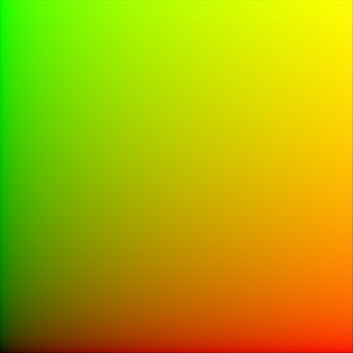
If you connect the UVs of an (unwrapped) plane to a shader’s colour, this is what you’ll see. Basically, texture coordinates are simply an ‘image’ of sorts, where the red value corresponds to the X-axis, and the green value corresponds to the Y-axis (and for 3d coordinates like Generated or Object, blue is the Z-axis.)
Why do we care?
It allows us to manipulate these coordinates as if they were colours (which I suppose they are):
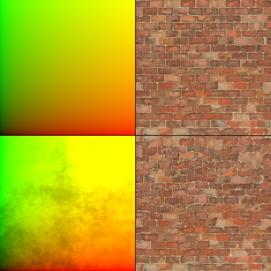
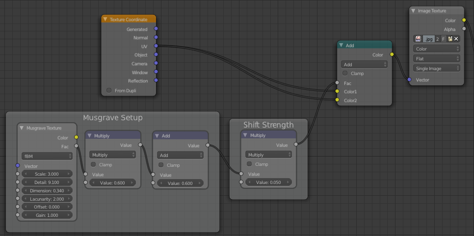
Here I’ve simply added a Musgrave texture to the UVs, and plugged that into the Vector input of the image texture:
Don’t forget that, except in the case of shaders, a socket’s colour is only a visual indication of the data it gives/takes and not a strict law – vectors and colours are essentially the same thing, three values, hence we can mix them up and use them together.
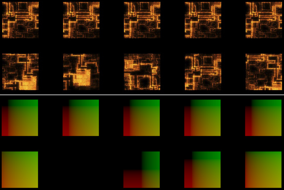
But those bricks look ugly you say? Well yeah. A more practical example would be to use the Random output of the Object Info node (yeah, again) to give each object (which have the same UVs) different offsets – so if you have a billion objects that are all the same, an easy way to break up the repetitiveness is to change the texture coordinates of each of them randomly.
That’s all folks!
I’m trying to post these ‘Commonly Ignored Features‘ twice a week, so let me know if you think of something I could share!